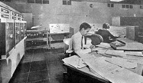
Fig. 81. N.G.T.E. computer installation (SDS 9300)
Information and photos on this page only are downloaded from www.ngte.co.uk as a local backup copy about the PDP-7 and SDS 9300 computers. ©2007 Simon Cornwell of www.ngte.co.uk and © Procurement Executive, Ministry Of Defence.
Engine operation during transient acceleration cycles can be measured in addition to the usual performance observations under steady state conditions, and all engine test information is normally fed through an on-line SDS 9300 computer with a PDP7 unit for data acquisition in support. The details of the instrumentation services are listed more comprehensively in paragraph 23.
Two groups of instruments measure engine test data, the first group give a direct display in the cell control room of engine and plant behaviour and are used to set-up and control the test in progress. The second group are installed to monitor more concisely the engine and plant parameters which are used to calculate test performance data. This latter group of instruments relay their information to the SDS 9300 computer which records and calculates test data according to prearranged software programs.

Fig. 81. N.G.T.E. computer installation (SDS 9300)
Figure 81 shows the main computer installation being operated during a test run. In steady state performance work, minimum accuracies of 0.25 per cent of full scale deflection are required, but in fact values of 0.1 per cent are frequently achieved. The arrangement of the steady state instrumentation is shown diagrammatically in Figure 82. The various measurements are fed to an electronic analogue-digital converter via a switching system and amplifier. The 17 digit output of the converted signal is then fed to the computer room.
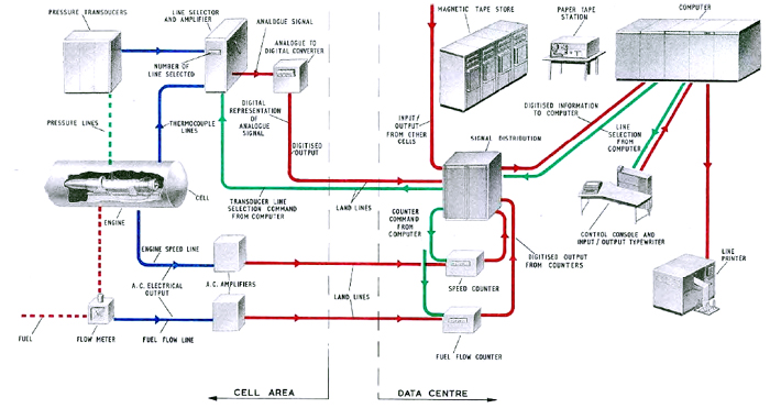
Fig. 82. Steady state instrumentation arrangement (SDS 9300)
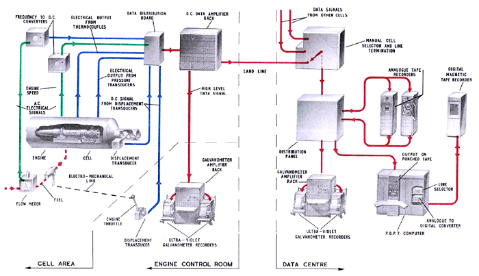
Fig. 83. Transient instrumentation arrangement (PDP-7)
The transient instrumentation system is shown in Figure 83. DC signals from the various sensors and transducers are fed into a data distribution board from which ultra violet galvanometer recorders, analogue tape recorders and a computer are fed in parallel. Magnetic tape recording of the transient conditions is produced in the computer room and can be used as an input to the computer when required. By using the UV recording units, on-line visual examination may be made both in the control room and in the data centre. In addition, other visual systems such as chart recorders and decimal displays are installed.
The computer itself is programmed to work ON-LINE and individual points are evaluated immediately. The computer has stored within itself all necessary calibrations and one of its tasks after the input information is collected is to convert this data into engineering units, e.g. lb/in2, degrees absolute, gal/min, etc. After meaning or averaging, selected data may be used to compute performance parameters ready for plotting the engine's performance curves. The maximum speed of data acquisition for steady state work is 100 points a second.
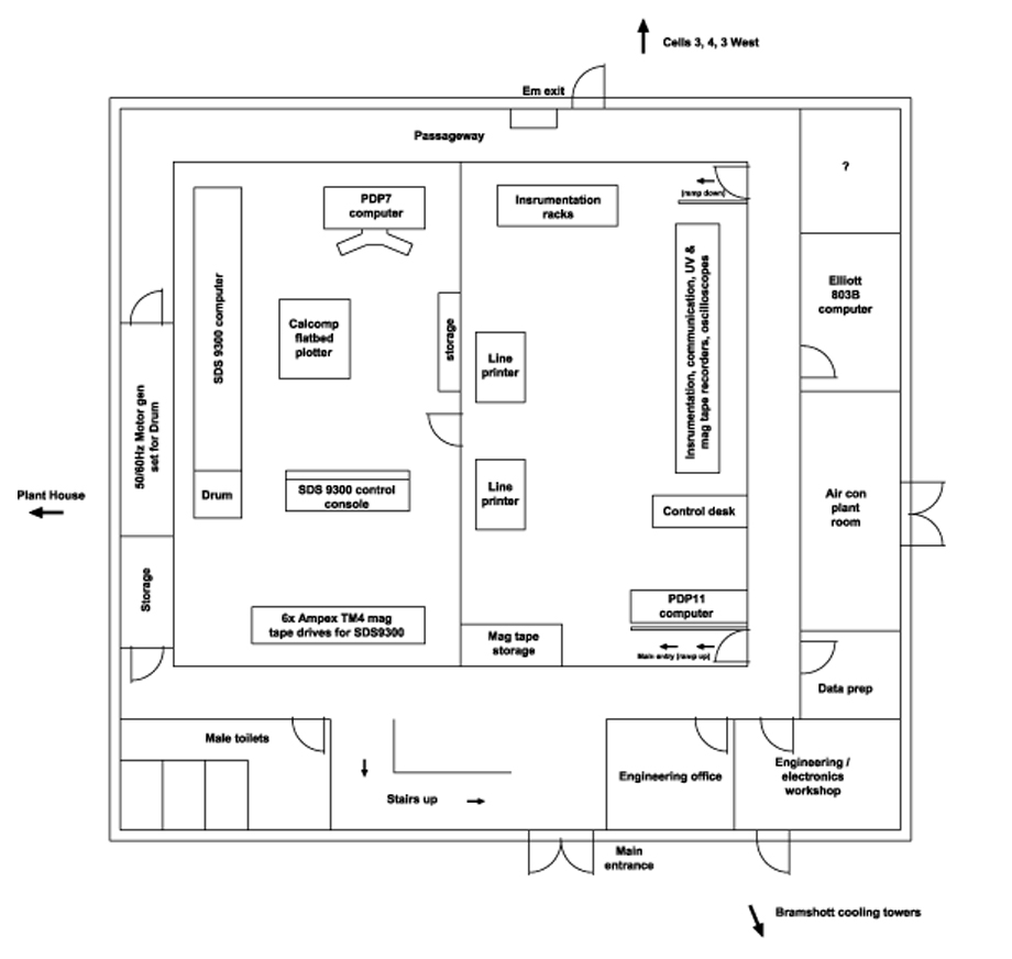
Computer room layout circa late 1960s early 70s.
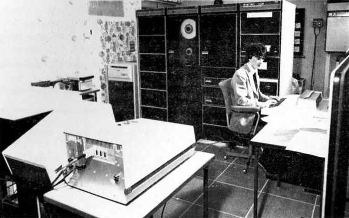
PDP11-45 computer installation.
The location of this system corresponds closely with the computer room layout drawing above, but the photo would appear to be sometime later as the "Cat" wall paper to the left of the computer was certainly not there in my time! The space in the photo occupied by the operator and terminal was at one time occupied by a large Calcomp flatbed plotter. That same plotter had also been located at another time (as the main computer room layout drawing shows) in the space between the SDS 9300 and the DEC PDP-7.
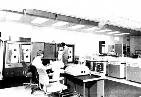
Later computer room layout with the ICL 1904S
The photo above is taken from a similar angle to the Fig.81 photo at the top of the page, but at a much later date as the ICL 1904S now occupies the space where SDS 9300 mainframe cabinets once were.
Site design ©2007- - privacy -