Prüfgeräte
Tester 8601A
Prüfgerät EFA381 - 8601a
The Soemtron Factory Prüfgerät EFA381 - 8601a
Skip to navigation |
 Soemtron 8601a Click an image for a larger version |
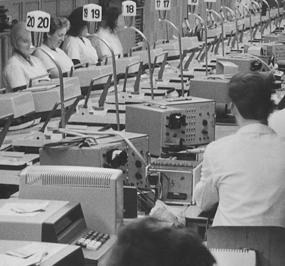 ETR220 production testing |
January 2022 - There was a time that we thought none of the original Soemtron Prüfgeräte equipment had survived the factory closure, and that was one of the main reasons why we had designed and built our own tester. However we were recently contacted by Frank Z. in Germany who had listed an 8601a Prüfgerät on Ebay, from an estate sale containing a collection of old radios, tape recorders, vinyl players and other equipment.
In the Russian technical manual for the Soemtron ETR220, Chapter 5 “Maintenance”, from a short section reproduced here, it details the use of a "Prüfgerät" in the case of faults that cannot be diagnosed with the logic diagrams, describing that - “the display panel of an electronic invoice machine « Soemtron-381 » of the type 8601 is connected”.
Frank has very graciously passed on this tester to us here at the Soemtron website, so that we can add it to the collection. It is configured for testing an EFA381 Invoicing machine but does have two extra supplementary panels for an EAA 383A/385Z and an EAA 382/385. As it does appear in photos for the ETR220 production line there must also have been other supplementary panels for the ETR22x range.
Originally designed for testing an EFA381 invoicing machine and manufactured by RFT, it is in a very good overall condition, includes the main test lead and comes in a leather carry case, so it is presumed to have been a piece of field engineers equipment. Both the carry case and the tester show signs of extensive use. It's hoped that with a good clean both inside and out and some repair to the case leather that it will be in operational order after electrical tests.

If you have any further historical information, circuits, drawings, photographs, data or manuals about the Soemtron ETR220, 221, 222 and 224 or their manufacture, test equipment (Prüfgeräte) or you just know more about the Soemtron companies in general then please let us know, contact us.
|
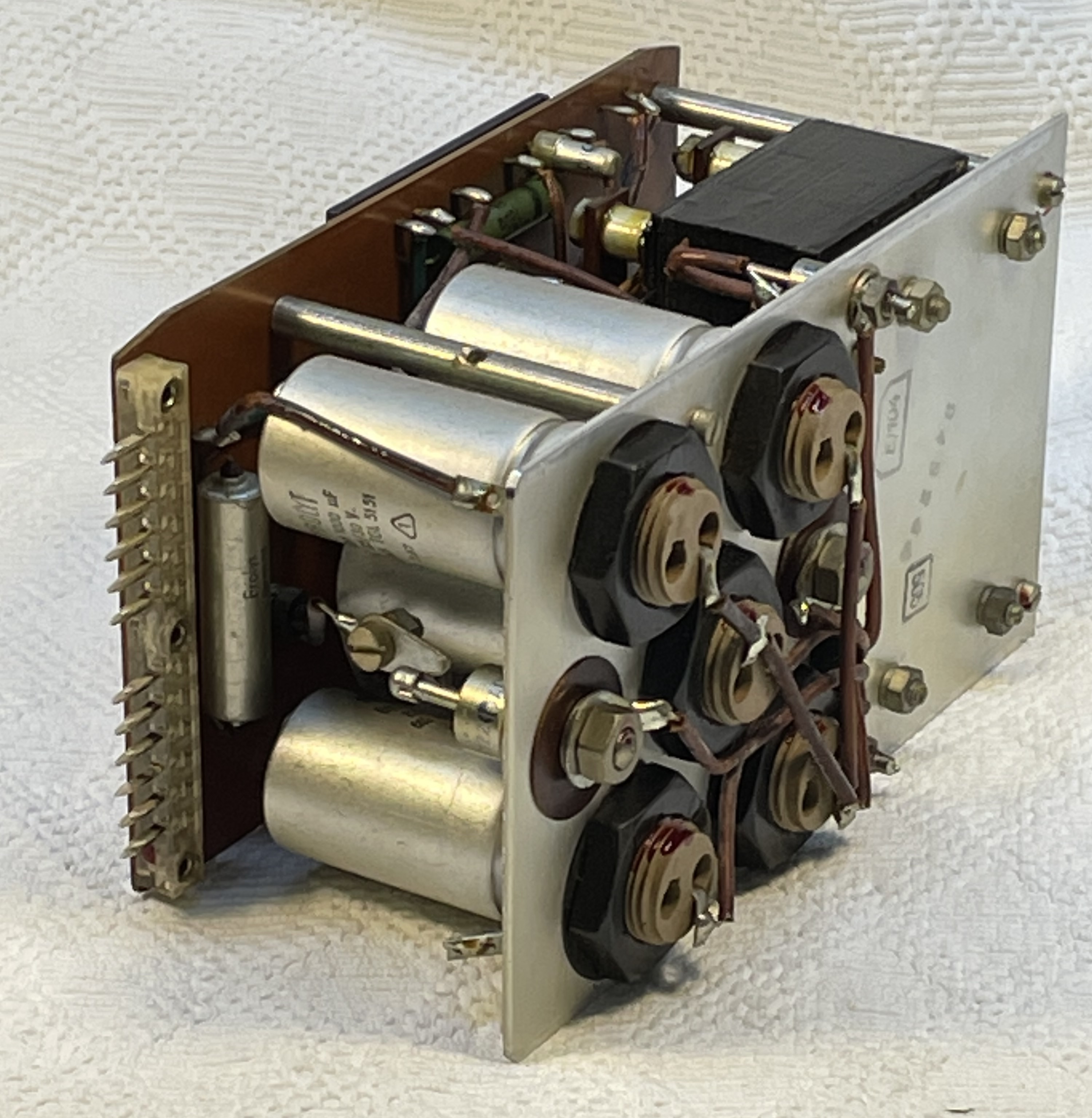
 General interior view Click any image for a larger image |
 Quality marking |
S#2000 - Technical Description
All images ©www.soemtron.org
Chassis - circuit
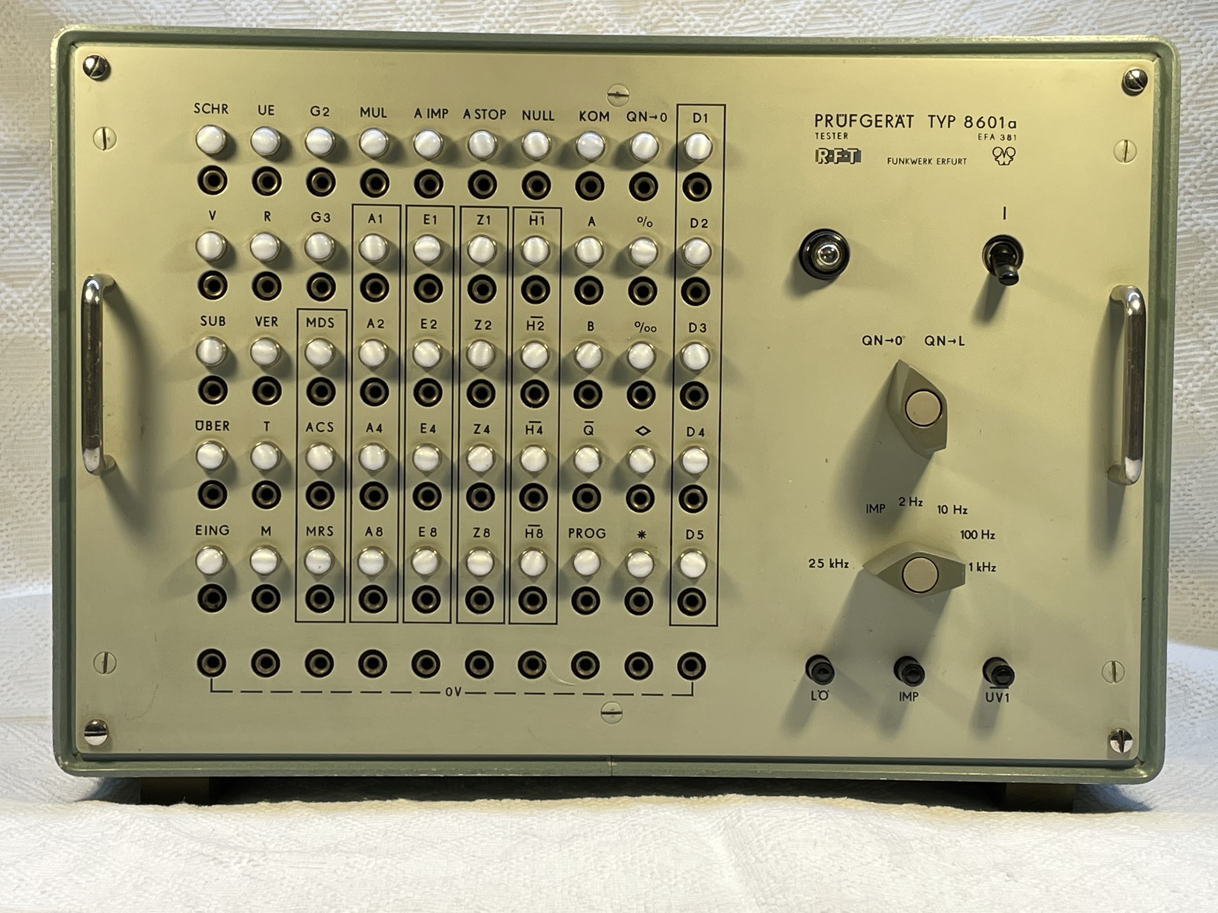
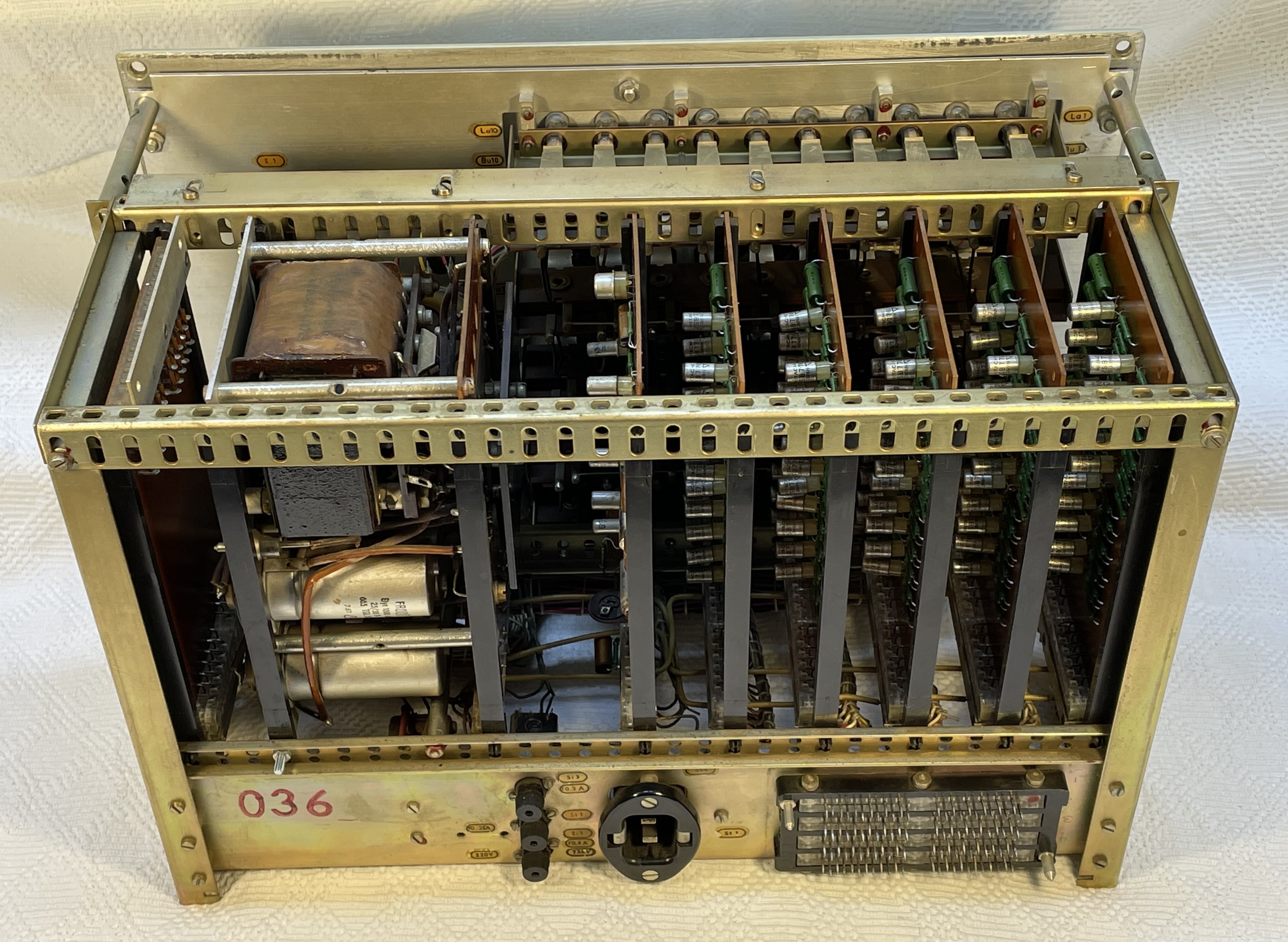
The Prüfgerät 8601a has an internal card cage/chassis assembly loaded with five, 10 channel sensor-lamp driver boards, a master oscillator-one shot board, power supply, and an extender card for servicing the unit.
There is a large 96 pin connector to the rear which forms the interface connection via a 2M cable to twin standard 32 pin plug connectors for the unit under test. Front panel switches allow the master clock to be slowed from the standard 25kHz to 1kHz, 100Hz, 10Hz and 2Hz. If needed a single step function can also be selected to further enable fault diagnosis. Three push buttons are for the master device reset (Lö), single step and to set the inverted UV1 signal. Another rotary switch sets the signal QN to LOW or passes it through for display.
Other than a common 0V connection, voltage supplies for 8601a are totally independent of the unit being tested. Construction is well engineered and sturdy, at the expense of being rather heavy for field service applications. It is marked - "Fabr. Nr. 2000, Funkwerk Erfurt Geprüft Kontrolle 14", and is dated 21-3-68. The rear of the chassis is marked "036".
|
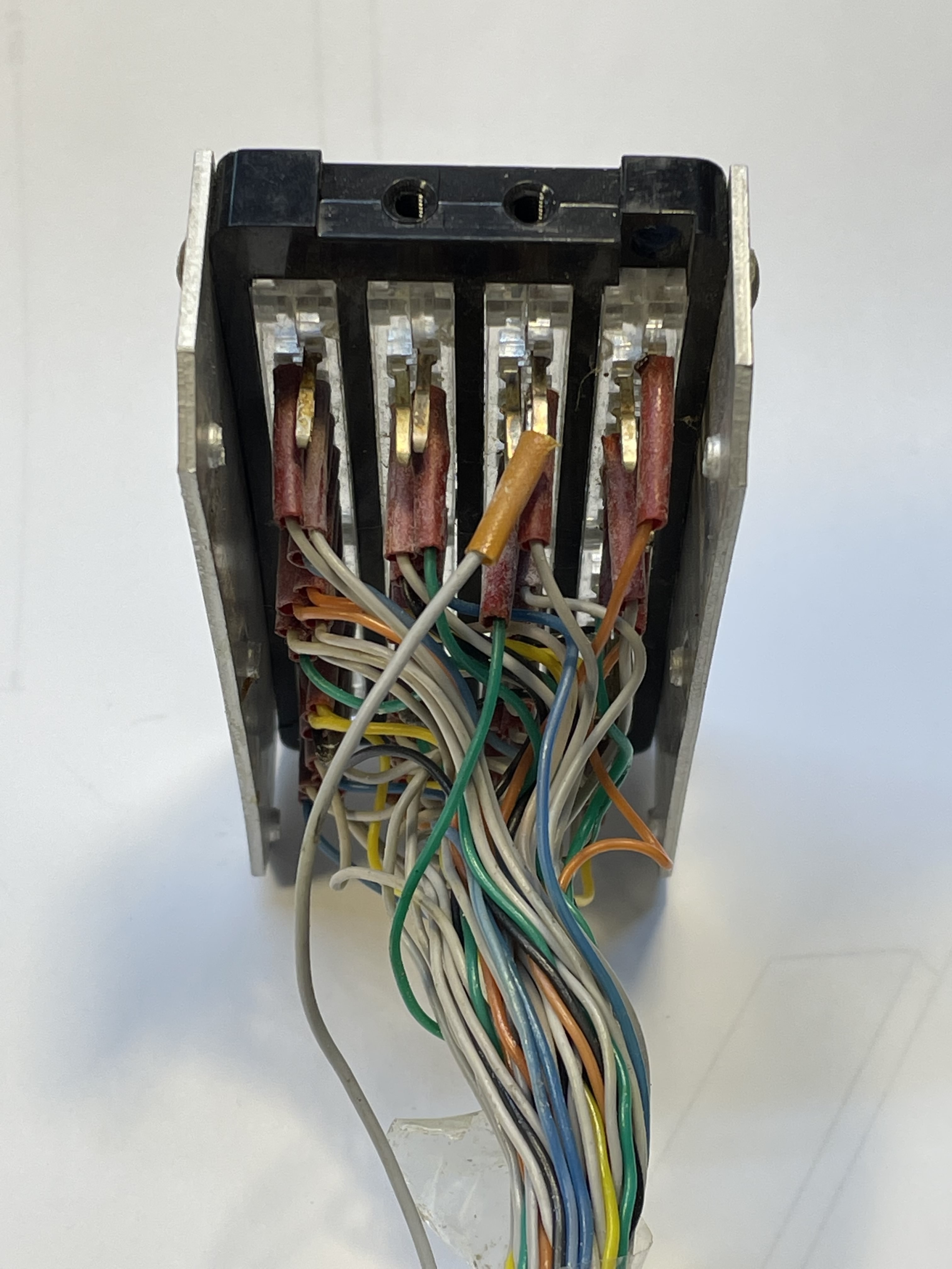
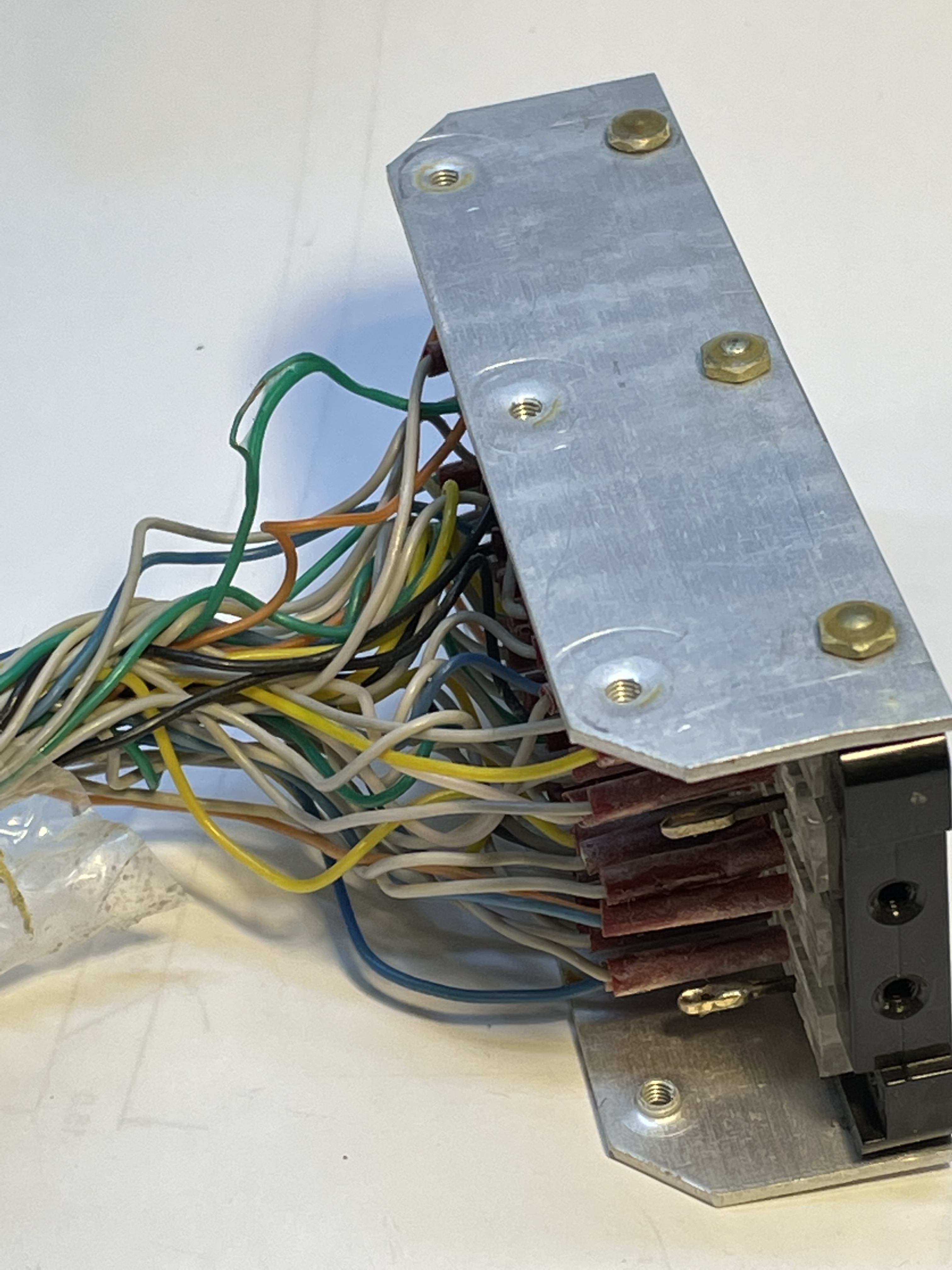
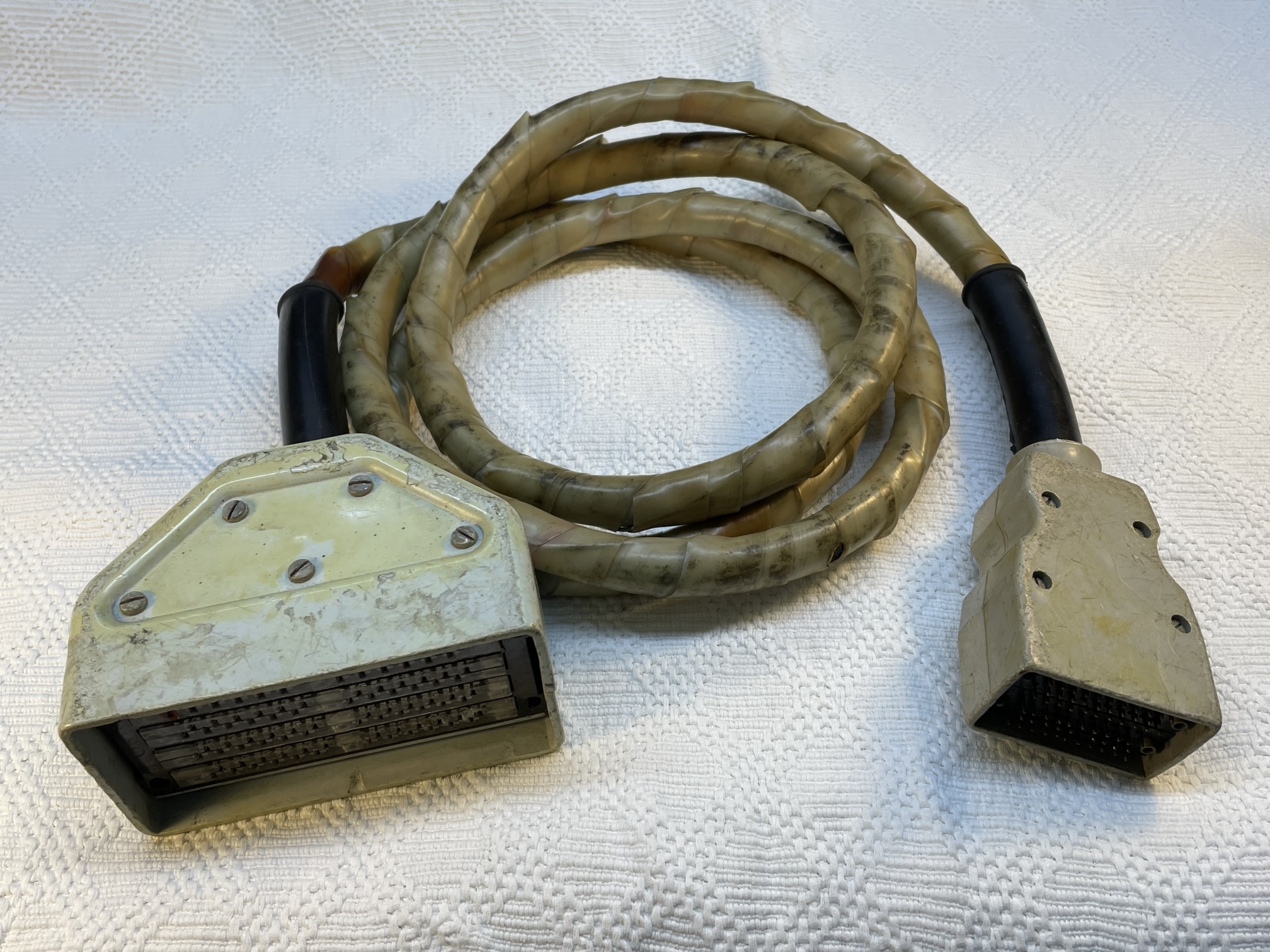 Prüfgerät 8601a test cable - See damage in the photos below |
Unit under test cable - connection matrix
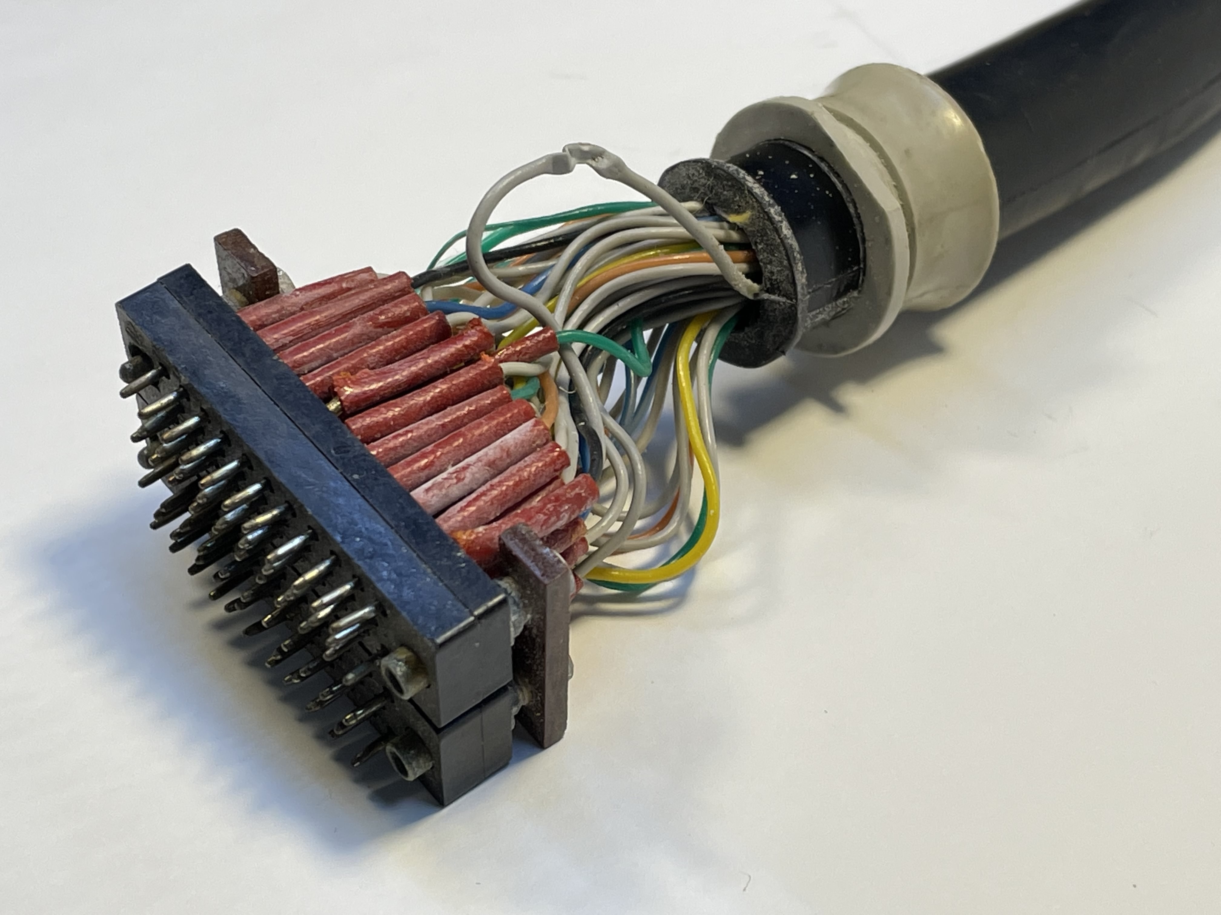
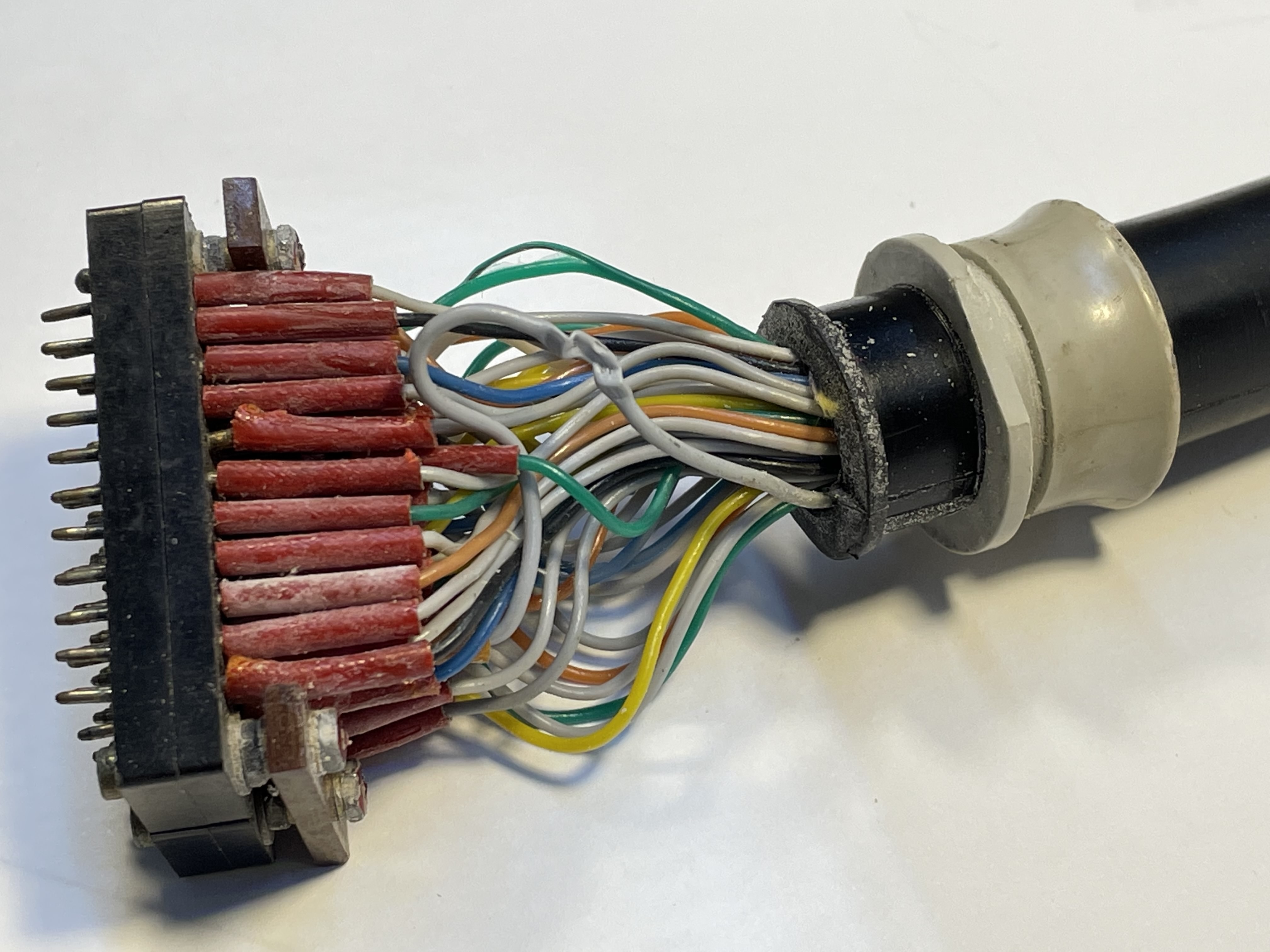
The 8601a's 55 way unit under test cable shows extensive usage and some modification with an extra external wire added. It consists of a 96 way plug constructed from four 24 pin plugs, a 55 way cable terminating in two 32 pin plug housings for the unit under test, both ends are housed in two mirrored plastic shells bolted together. At some point in its life the whole assembly has suffered a high current overload event in the common ground connection resulting in over heating of the exposed wiring close to the connectors, presumably from a faulty piece of equipment under test.
Also the addition of an extra external wire with a further subsidiary covering was found to have been trapped and squashed in the connector shells at the 64 pin (device under test) end. All of these faults can be seen in the photos below. Along with several other dry joints found in the assemblies, the cable has been repaired and is now fully functional.
The connection matrix (link above), has mechanical diagrams for the Prüfgerät and device under test connectors, along with a connection matrix for the cable. There is also a matrix showing the relationship for the display rows to the device under test connectors.
 96 way connector end with dry joint |
 96 way connector end burnt ground wiring |
 64 way connector end trapped/squashed wiring |
 64 way connector end burnt ground wiring |
| Click any image for a larger version | |||
|
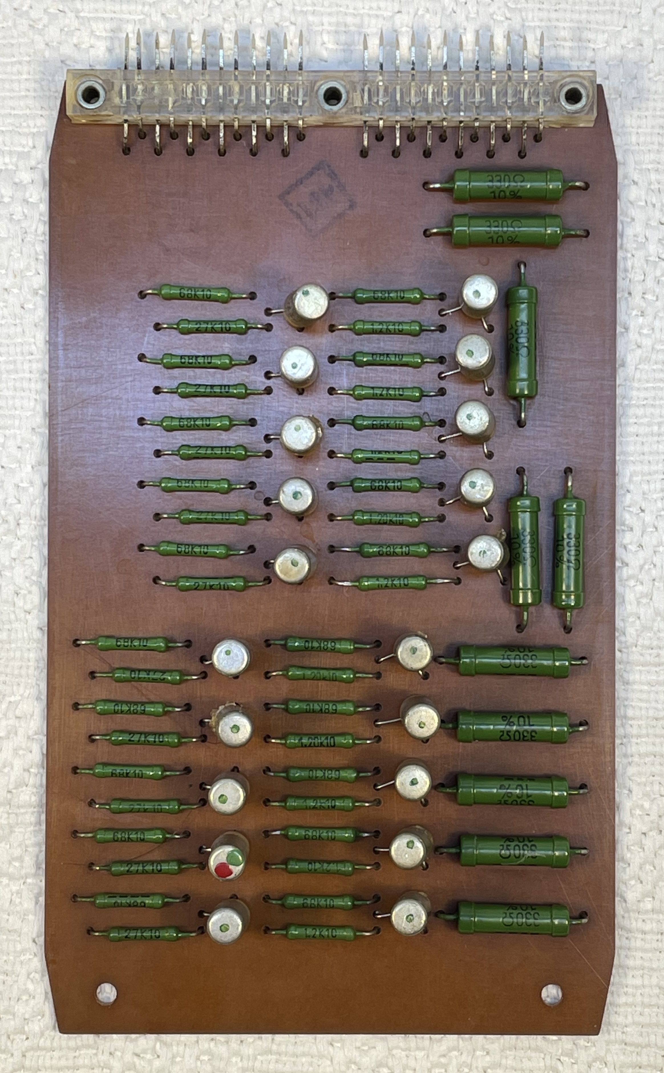 10 channel sensor / lamp driver card |
10 channel sensor-lamp driver board - circuit
The channel sensor-lamp driver board contains 10 Darlington (cascaded emitter follower) amplifiers utilising paired 2SB77 PNP transistors.
Each driver channel senses one signal from the device being tested, displaying the result at the front panel with a T5.5 telephone slide lamp of 12V 50mA rating. A 330R resistor in each driver provides a bias current to keep the lamp filament warm when the lamp is not energised, this helps (supposedly ?) to prolong the lamp's lifetime. With a Darlington configuration the overall current gain of the pair is the sum of the individual transistor's gain (β=β1*β2), so achieving a relatively high input impedance and current gain in a circuit with the minimum number of components.
Each board caters for one row of lamps in the display; board 1 (far left in the card cage) is for the top row, board 2 for row 2, and so on. The main front panel can be hinged forward to allow replacement of the indicator lamps if needed, however this could also be accomplished from the front by removing the lamp's lens and using a suitable extractor tool for the indicator.
|
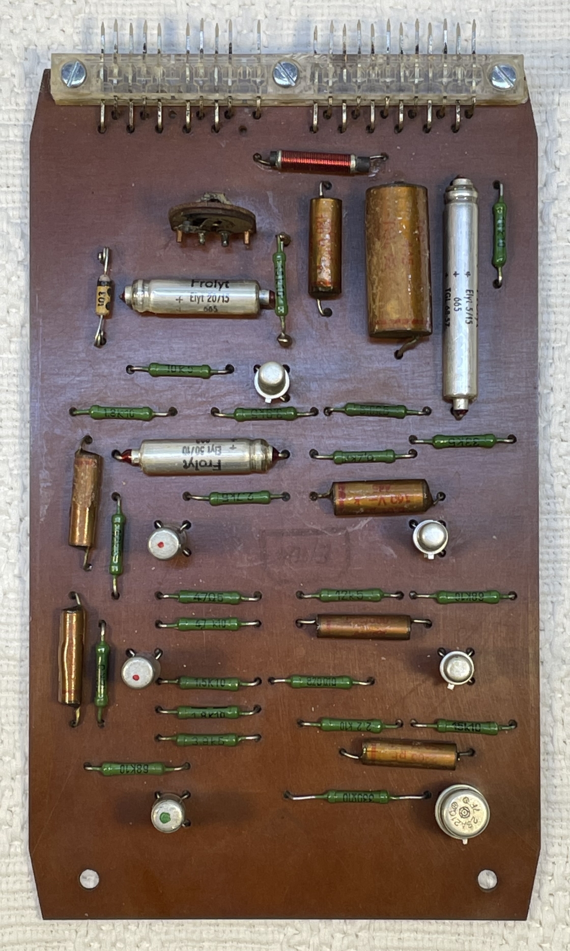 Master oscillator card |
Master oscillator-one shot - circuit
Board 6 in the card cage is the master oscillator and one shot signal generator providing the front panel selectable ranges of test clock frequencies used in fault finding a unit under test whether it be an ETR22x[1] calculator, electronic invoice machine or other equipment made by V.E.B.[2] Büromaschinenwerk[3] Sömmerda.
On testing our 8601a we found that the switch selectable frequencies were not as per the values indicated by the switch selection, a couple were wildly out. EG - 25kHz = 55.3kHz, 1kHz = 163Hz, 100Hz = 19.9Hz, 10Hz = 13.9Hz, 2Hz = 2.6Hz.
All these discrepancies were found to be age related degradation of the indicated value of the capacitors, each being measured with a Wayne Kerr L-C-R bridge. All of the range selection capacitors have been replaced with new components bringing the frequencies back to within 5% of their indicated values using a Tektronix TDS380 oscilloscope in frequency measurement mode.
|
< Power supply - diagram |
Power supply basic wiring
The power supply is a standard linear unit providing independent, isolated +12V and -12V supplies, and a lamp supply. Given the complex ladder type construction of the unit, which would necessitate extensive dis-assembly, no circuit diagram has been produced at this time. The main circuit provides a basic outline of the power supply system (on page 3) and its place in the overall layout of the 8601a unit.
The lamp supply is notionally -20V with no lamps installed, however with the 330R bleed or "black light" resistor in each lamp circuit, the supply sits at a nominal -11V with all lamps installed and no input signals. These resistors serve to keep the lamp filaments relatively warm prolonging their life.
|
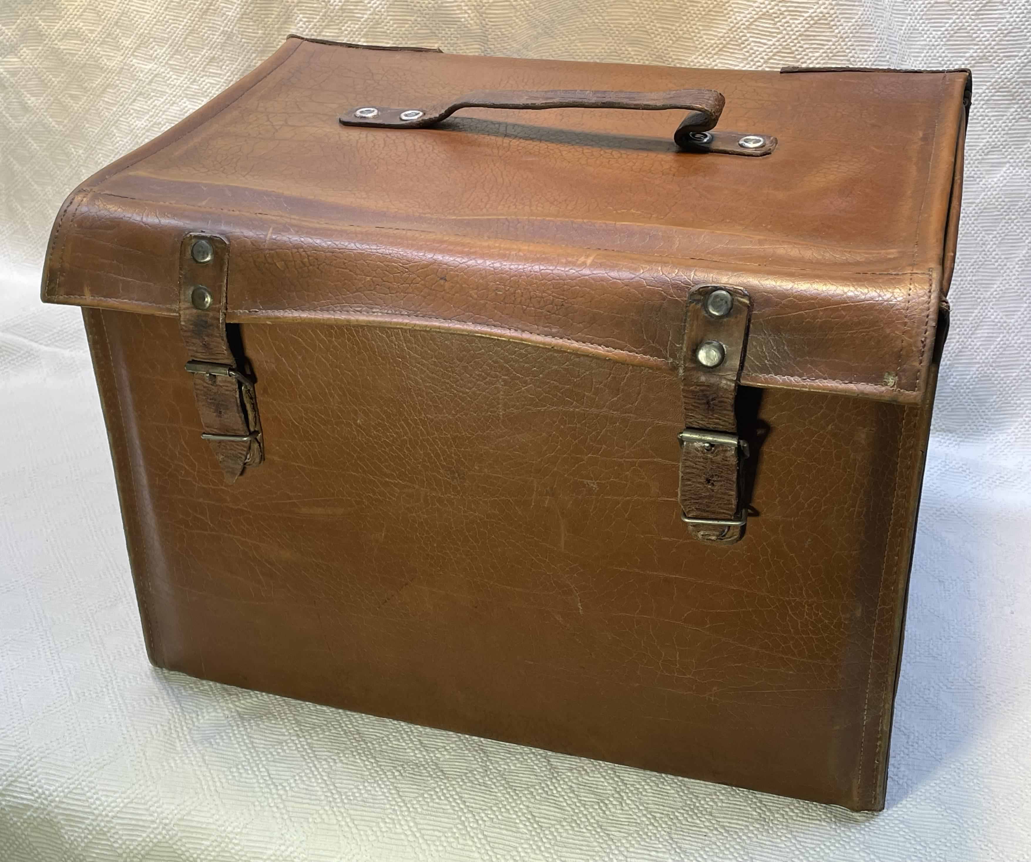 Carry case |
Carry case
Our 8601a came from Frank Z. in Germany who had listed the 8601 Prüfgerät on Ebay, from an estate sale containing a collection of old radios, tape recorders, vinyl players and other equipment. It came with a well used leather carrying case so we presume the unit was a field engineers unit probably mainly used for the repair of the EFA 380 series of Fakturierautomaten (Invoicing machines).
It had signs of heavy usage with lots of nicks and scratches, stains, the top cover was split from both sides at the hinge point and a lot of the stitching had come undone. All of these small problems have been dealt with, the splits have been repaired and the leather has been treated with saddle soap to rejuvenate it, and then polished.
| 1 | ETR | Elektronischer Tischrechner[back] [top] |
| 2 | Wikipedia entry for V.E.B. = Volks Eigener Betrieb, or Peoples Owned Company | V.E.B.[back] [top] |
| 3 | Büromaschinenwerk | Office Machine Works[back] [top] |
Site design ©2007- - privacy -